Showing posts with label SITRC. Show all posts

Saturday, 27 July 2013

Getting Started with Arduino

What is Arduino?

Arduino is a tool for making computers that can sense and control more of the physical world than your desktop computer. It's an open-source physical computing platform based on a simple microcontroller board, and a development environment for writing software for the board.
Arduino can be used to develop interactive objects, taking inputs from a variety of switches or sensors, and controlling a variety of lights, motors, and other physical outputs. Arduino projects can be stand-alone, or they can be communicate with software running on your computer (e.g. Flash, Processing, MaxMSP.) The boards can be assembled by hand or purchased preassembled; the open-source IDE can be downloaded for free.
The Arduino programming language is an implementation of Wiring, a similar physical computing platform, which is based on the Processing multimedia programming environment.

Why Arduino?

There are many other microcontrollers and microcontroller platforms available for physical computing. Parallax Basic Stamp, Netmedia's BX-24, Phidgets, MIT's Handyboard, and many others offer similar functionality. All of these tools take the messy details of microcontroller programming and wrap it up in an easy-to-use package. Arduino also simplifies the process of working with microcontrollers, but it offers some advantage for teachers, students, and interested amateurs over other systems:
  • Inexpensive - Arduino boards are relatively inexpensive compared to other microcontroller platforms. The least expensive version of the Arduino module can be assembled by hand, and even the pre-assembled Arduino modules cost less than $50
  • Cross-platform - The Arduino software runs on Windows, Macintosh OSX, and Linux operating systems. Most microcontroller systems are limited to Windows.
  • Simple, clear programming environment - The Arduino programming environment is easy-to-use for beginners, yet flexible enough for advanced users to take advantage of as well. For teachers, it's conveniently based on the Processing programming environment, so students learning to program in that environment will be familiar with the look and feel of Arduino
  • Open source and extensible software- The Arduino software is published as open source tools, available for extension by experienced programmers. The language can be expanded through C++ libraries, and people wanting to understand the technical details can make the leap from Arduino to the AVR C programming language on which it's based. SImilarly, you can add AVR-C code directly into your Arduino programs if you want to.
  • Open source and extensible hardware - The Arduino is based on Atmel's ATMEGA8  and ATMEGA168microcontrollers. The plans for the modules are published under a Creative Commons license, so experienced circuit designers can make their own version of the module, extending it and improving it. Even relatively inexperienced users can build the breadboard version of the module in order to understand how it works and save money.

1 | Get an Arduino board and USB cable

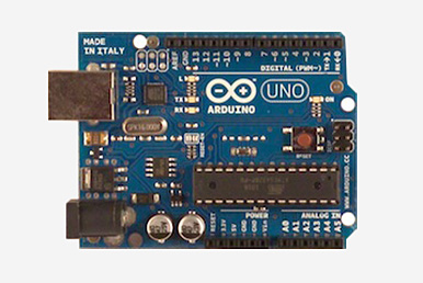
We assume you're using an Arduino Uno, Arduino Duemilanove, Nano, Arduino Mega 2560 , or Diecimila. If you have another board, read the corresponding page in this getting started guide.
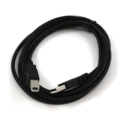
You also need a standard USB cable (A plug to B plug): the kind you would connect to a USB printer.


2 | Download the Arduino environment

Get the latest version from the download page.
When the download finishes, unzip the downloaded file. Make sure to preserve the folder structure. Double-click the folder to open it. There should be a few files and sub-folders inside.

3 | Connect the board

The Arduino Uno, Mega, Duemilanove and Arduino Nano automatically draw power from either the USB connection to the computer or an external power supply. If you're using an Arduino Diecimila, you'll need to make sure that the board is configured to draw power from the USB connection. The power source is selected with a jumper, a small piece of plastic that fits onto two of the three pins between the USB and power jacks. Check that it's on the two pins closest to the USB port.
Connect the Arduino board to your computer using the USB cable. The green power LED (labelled PWR) should go on.

4 | Install the drivers

Installing drivers for the Arduino Uno or Arduino Mega 2560 with Windows7, Vista, or XP:
·         Plug in your board and wait for Windows to begin it's driver installation process.  After a few moments, the process will fail, despite its best efforts
·         Click on the Start Menu, and open up the Control Panel.
·         While in the Control Panel, navigate to System and Security. Next, click on System. Once the System window is up, open the Device Manager.
·         Look under Ports (COM & LPT).  You should see an open port named "Arduino UNO (COMxx)"
·         Right click on the "Arduino UNO (COmxx)" port and choose the "Update Driver Software" option.
·         Next, choose the "Browse my computer for Driver software" option.
·         Finally, navigate to and select the driver file named "arduino.inf", located in the "Drivers" folder of the Arduino Software download (not the "FTDI USB Drivers" sub-directory). If you are using an old version of the IDE (1.0.3 or older), choose the Uno's driver file named "Arduino UNO.inf"
·         Windows will finish up the driver installation from there.

5 | Launch the Arduino application

Double-click the Arduino application. (Note: if the Arduino software loads in the wrong language, you can change it in the preferences dialog.)

6 | Open the blink example

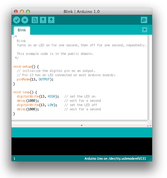
Open the LED blink example sketch: File > Examples > 1.Basics > Blink.

7 | Select your board

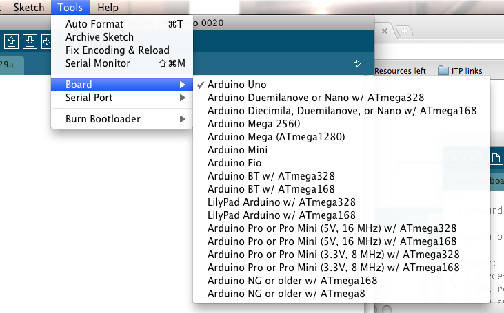
You'll need to select the entry in the Tools > Board menu that corresponds to your Arduino.

Selecting an Arduino Uno
For Duemilanove Arduino boards with an ATmega328 (check the text on the chip on the board), select Arduino Duemilanove or Nano w/ ATmega328. Previously, Arduino boards came with an ATmega168; for those, selectArduino Diecimila, Duemilanove, or Nano w/ ATmega168.

8 | Select your serial port
Select the serial device of the Arduino board from the Tools | Serial Port menu. This is likely to be COM3 or higher (COM1 and COM2 are usually reserved for hardware serial ports). To find out, you can disconnect your Arduino board and re-open the menu; the entry that disappears should be the Arduino board. Reconnect the board and select that serial port.

9 | Upload the program

Now, simply click the "Upload" button in the environment. Wait a few seconds - you should see the RX and TX leds on the board flashing. If the upload is successful, the message "Done uploading." will appear in the status bar. 

A few seconds after the upload finishes, you should see the pin 13 (L) LED on the board start to blink (in orange). If it does, congratulations! You've gotten Arduino up-and-running.

Thursday, 25 July 2013

Operational amplifier (op-amp)

An operational amplifier (op-amp) is a DC-coupled high-gain electronic voltage amplifier with a differential input and, usually, a single-ended output. In this configuration, an op-amp produces an output potential (relative to circuit ground) that is typically hundreds of thousands of times larger than the potential difference between its input terminals.
Operational amplifiers had their origins in analog computers, where they were used to do mathematical operations in many linear, non-linear and frequency-dependent circuits. Characteristics of a circuit using an op-amp are set by external components with little dependence on temperature changes or manufacturing variations in the op-amp itself, which makes op-amps popular building blocks for circuit design.
Op-amps are among the most widely used electronic devices today, being used in a vast array of consumer, industrial, and scientific devices. Many standard IC op-amps cost only a few cents in moderate production volume; however some integrated or hybrid operational amplifiers with special performance specifications may cost over $100 US in small quantities. Op-amps may be packaged as components, or used as elements of more complex integrated circuits.
The op-amp is one type of differential amplifier. Other types of differential amplifier include the fully differential amplifier (similar to the op-amp, but with two outputs), the instrumentation amplifier (usually built from three op-amps), the isolation amplifier (similar to the instrumentation amplifier, but with tolerance to common-mode voltages that would destroy an ordinary op-amp), and negative feedback amplifier (usually built from one or more op-amps and a resistive feedback network).

Circuit Notation
The circuit symbol for an op-amp is shown to the right, where:
  • V+: non-inverting input
  • V: inverting input
  • Vout: output
  • VS+: positive power supply
  • VS−: negative power supply
The power supply pins (VS+ and VS−) can be labeled in different ways. Often these pins are left out of the diagram for clarity, and the power configuration is described or assumed from the circuit.

OPERATION
The amplifier's differential inputs consist of a V+ input and a V input, and ideally the op-amp amplifies only the difference in voltage between the two, which is called the differential input voltage. The output voltage of the op-amp is given by the equation:
V_{\!\text{out}} = A_{OL} \, (V_{\!+} - V_{\!-})
where V+ is the voltage at the non-inverting terminal, V is the voltage at the inverting terminal and AOL is the open-loop gain of the amplifier (the term "open-loop" refers to the absence of a feedback loop from the output to the input).
The magnitude of AOL is typically very large—100,000 or more for integrated circuit op-amps—and therefore even a quite small difference between V+and V drives the amplifier output nearly to the supply voltage. Situations in which the output voltage is equal to or greater than the supply voltage are referred to as saturation of the amplifier. The magnitude of AOL is not well controlled by the manufacturing process, and so it is impractical to use an operational amplifier as a stand-alone differential amplifier. Without negative feedback, and perhaps with positive feedback for regeneration, an op-amp acts as a comparator. If the inverting input is held at ground (0 V) directly or by a resistor, and the input voltage Vin applied to the non-inverting input is positive, the output will be maximum positive; if Vin is negative, the output will be maximum negative. Since there is no feedback from the output to either input, this is an open loop circuit acting as a comparator. The circuit's gain is just the AOL of the op-amp.

If predictable operation is desired, negative feedback is used, by applying a portion of the output voltage to the inverting input. The closed loop feedback greatly reduces the gain of the amplifier. When negative feedback is used, the circuit's overall gain and response becomes determined mostly by the feedback network rather than by the op-amp itself. If the feedback network is made of components with relatively constant, stable values, the variability of the op-amp's open loop response does not seriously affect the circuit's performance. The response of the op-amp circuit with its input, output and feedback circuits to an input is characterized mathematically by a transfer function. Designing an op-amp circuit to have a desired transfer function is in the realm of electrical engineering. The transfer functions are important in most applications of op-amps, such as in analog computers. High inputimpedance at the input terminals and low output impedance at the output terminal(s) are particularly useful features of an op-amp.
For example, in a non-inverting amplifier (see the figure on the right) adding a negative feedback via the voltage divider RfRg reduces the gain. Equilibrium will be established when Vout is just sufficient to reach around and "pull" the inverting input to the same voltage as Vin. The voltage gain of the entire circuit is determined by 1 + Rf/Rg. As a simple example, if Vin = 1 V and Rf = Rg, Vout will be 2 V, the amount required to keep V at 1 V. Because of the feedback provided by RfRg this is a closed loop circuit. Its overall gain Vout / Vin is called the closed-loop gain ACL. Because the feedback is negative, in this case ACL is less than the AOL of the op-amp.
Another way of looking at it is to make two relatively valid assumptions.

One, that when an op-amp is being operated in linear (not saturated) mode, the difference in voltage between the non-inverting (+) pin and the inverting (−) pin is so small as to be considered negligible

The second assumption is that the input impedance at both (+) and (−) pins is extremely high (at least several megohms with modern op-amps).
Thus, when the circuit to the right is operated as a non-inverting linear amplifier, Vin will appear at the (+) and (−) pins and create a current i through Rg equal to Vin/Rg. Since Kirchhoff's current law states that the same current must leave a node as enter it, and since the impedance into the (−) pin is near infinity, we can assume the overwhelming majority of the same current i travels through Rf, creating an output voltage equal to Vin + i × Rf. By combining terms, we can easily determine the gain of this particular type of circuit.

i = \frac {V_\text{in}} {R_g}
V_\text{out} = V_\text{in} + i \times R_f = V_\text{in} + \left(\frac {V_\text{in}} {R_g} \times R_f\right) = V_\text{in} + \frac{V_\text{in} \times R_f} {R_g} = V_\text{in}  \left(1 + \frac{R_f} {R_g}\right)
G = \frac{V_\text{out}} {V_\text{in}} = 1 + \frac{R_f} {R_g}
CHARACTERISTICS 
Real operational amplifiers suffer from several non-ideal effects:
    Finite gain
    Open-loop gain is infinite in the ideal operational amplifier but finite in real operational amplifiers. Typical devices exhibit open-loop DC gain ranging from 100,000 to over 1 million. So long as the loop gain (i.e., the product of open-loop and feedback gains) is very large, the circuit gain will be determined entirely by the amount of negative feedback (i.e., it will be independent of open-loop gain). In cases where closed-loop gain must be very high, the feedback gain will be very low, and the low feedback gain causes low loop gain; in these cases, the operational amplifier will cease to behave ideally.
    Finite input impedances
    The differential input impedance of the operational amplifier is defined as the impedance between its two inputs; the common-mode input impedance is the impedance from each input to ground. MOSFET-input operational amplifiers often have protection circuits that effectively short circuit any input differences greater than a small threshold, so the input impedance can appear to be very low in some tests. However, as long as these operational amplifiers are used in a typical high-gain negative feedback application, these protection circuits will be inactive. The input bias and leakage currents described below are a more important design parameter for typical operational amplifier applications.
    Non-zero output impedance
    Low output impedance is important for low-impedance loads; for these loads, the voltage drop across the output impedance of the amplifier will be significant. Hence, the output impedance of the amplifier limits the maximum power that can be provided. In configurations with a voltage-sensing negative feedback, the output impedance of the amplifier is effectively lowered; thus, in linear applications, op-amps usually exhibit a very low output impedance indeed. Negative feedback can not, however, reduce the limitations that Rload in conjunction with Rout place on the maximum and minimum possible output voltages; it can only reduce output errors within that range.
    Low-impedance outputs typically require high quiescent (i.e., idle) current in the output stage and will dissipate more power, so low-power designs may purposely sacrifice low output impedance.
    Input current
    Due to biasing requirements or leakage, a small amount of current (typically ~10 nanoamperes for bipolar op-amps, tens of picoamperes for JFET input stages, and only a few pA for MOSFET input stages) flows into the inputs. When large resistors or sources with high output impedances are used in the circuit, these small currents can produce large unmodeled voltage drops. If the input currents are matched, and the impedance looking out of both inputs are matched, then the voltages produced at each input will be equal. Because the operational amplifier operates on the difference between its inputs, these matched voltages will have no effect (unless the operational amplifier has poor CMRR, which is described below). It is more common for the input currents (or the impedances looking out of each input) to be slightly mismatched, and so a small offset voltage (different from the input offset voltage below) can be produced. This offset voltage can create offsets or drifting in the operational amplifier. It can often be nulled externally; however, many operational amplifiers include offset null or balance pins and some procedure for using them to remove this offset. Some operational amplifiers attempt to nullify this offset automatically.
    Input offset voltage
    This voltage, which is what is required across the op-amp's input terminals to drive the output voltage to zero,[6][nb 1] is related to the mismatches in input bias current. In the perfect amplifier, there would be no input offset voltage. However, it exists in actual op-amps because of imperfections in the differential amplifier that constitutes the input stage of the vast majority of these devices. Input offset voltage creates two problems: First, due to the amplifier's high voltage gain, it virtually assures that the amplifier output will go into saturation if it is operated without negative feedback, even when the input terminals are wired together. Second, in a closed loop, negative feedback configuration, the input offset voltage is amplified along with the signal and this may pose a problem if high precision DC amplification is required or if the input signal is very small.[nb 2]
    Common-mode gain
    A perfect operational amplifier amplifies only the voltage difference between its two inputs, completely rejecting all voltages that are common to both. However, the differential input stage of an operational amplifier is never perfect, leading to the amplification of these identical voltages to some degree. The standard measure of this defect is called the common-mode rejection ratio(denoted CMRR). Minimization of common mode gain is usually important in non-inverting amplifiers (described below) that operate at high amplification.
    Output sink current
    The output sink current is maximum current allowed to sink into the output stage. Some manufacturers show the output voltage vs. the output sink current plot, which gives an idea of the output voltage when it is sinking current from another source into the output pin.
    Temperature effects
    All parameters change with temperature. Temperature drift of the input offset voltage is especially important.
    Power-supply rejection
    The output of a perfect operational amplifier will be completely independent from ripples that arrive on its power supply inputs. Every real operational amplifier has a specified power supply rejection ratio (PSRR) that reflects how well the op-amp can reject changes in its supply voltage. Copious use of bypass capacitors can improve the PSRR of many devices, including the operational amplifier.
    Drift
    Real op-amp parameters are subject to slow change over time and with changes in temperature, input conditions, etc.
    Noise
    Amplifiers generate random voltage at the output even when there is no signal applied. This can be due to thermal noise and flicker noise of the devices. For applications with high gain or high bandwidth, noise becomes a very important consideration.


Thursday, 18 July 2013

Let commence with 8051.

Hay guys…
  Welcome to the micro world i.e.… 8051 one of the very familiar  stream of our branch . The whole story has its beginnings in the far 80s when Intel launched the first series of micro-controllers called the MCS 051. Even though these micro-controllers had quite modest features in comparison to the new ones, they conquered the world very soon and became a standard for what nowadays is called the micro-controller.
The main reason for their great success and popularity is a skillfully chosen configuration which satisfies different needs of a large number of users allowing at the same time constant expansions.

  • 4 Kb of ROM is not much at all.
  • 128b of RAM (including SFRs) satisfies the user's basic needs.
  • 4 ports having in total of 32 input/output lines are in most cases sufficient to make all necessary connections to peripheral environment.
The whole configuration is obviously thought of as to satisfy the needs of most programmers working on development of automation devices.
Here we are going for many more applications and interfacing of various devices e.g.- ADC , stepper motor etc .  and also share some tricks for configuring the various devices with 8051 .
The various tools available for the assessment of 8051 is keil, SPJ Terminal etc. We will also go for certain practical based implementation as assignment and much more.